|
|
|
|
A Step-by-Step Example : Schematic of CMOS inverter
In this example, we use basic Magic drawing command to layout the inverter. Start Sue from the Unix prompt:
prompt> sue
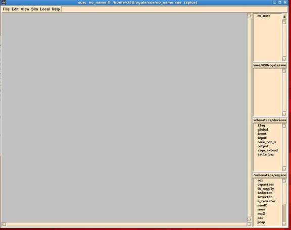
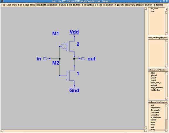
A window should come up which looks something like this:
Understanding the display window:
On the very top of the window the title bar should say:
sue: no_name S <path_to_cell> (spice)
"no_name" means that you have not specified the file you wish to edit. The "S" means that you are editing a "Schematic", as opposed to an ICON. Also, in parenthesis, you will see spice displayed. This means that you are currently in spice simulation mode.
Down the right side of the window are several small Library List boxes. The top one lists all current schematics that have been loaded into SUE. Currently only "no_name" should be listed. The next box is the Icon List Box. This Icon Library List box typically displays all of the Icons SUE has loaded for your current schematic. It should be blank for now. The next two Library List Boxes (Lib List) are typically used to display the Icons for various library elements. In this example the mspice and devices libraries are shown.
Drawing Schematic:
Pull down the File menu and select new schematic. This will bring up the File Select box. Note that you could have also used the hot key Ctrl-n to bring up this menu as well. Save file as "inv", or any other name you like. Click the OK. You should now see "inv" in the upper right Schematic List box, and in the title bar at the top of the window. The title bar tells you that you are editing "inv".
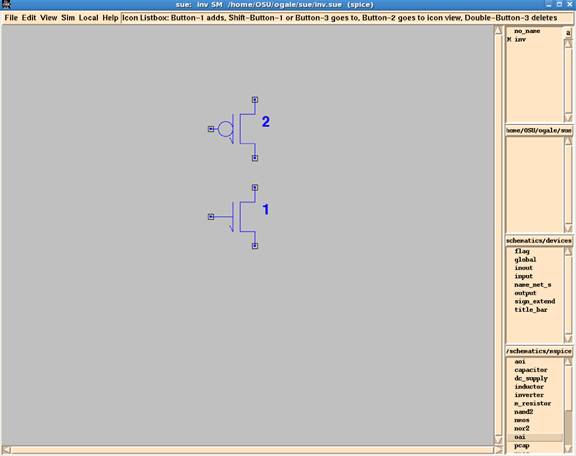
You should see something like this:
Notice that the numbers displayed (2 for PMOS and 1 for NMOS) indicate widths of the transistors.
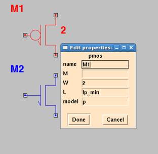
Your schematic should look something like this:
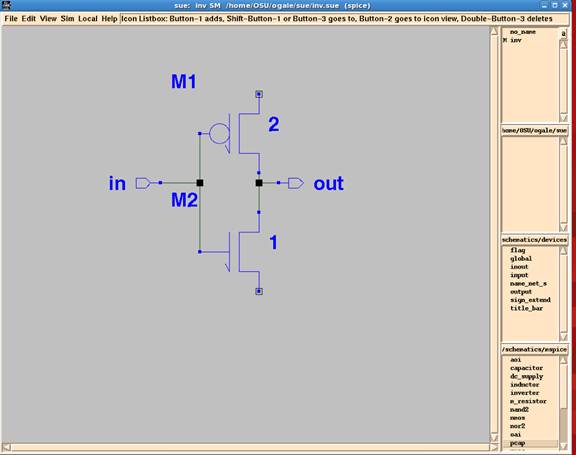
This completes our inverter schematic. The complete schematic should look like this:
Extracting Simulation FilesSpice netlist:Select SPICE Netlist or press Shift+n from Sim menu on the panel. This will write spice netlist for you. You can run this netlist with HSPICE..Sim File:Sue opens in Spice mode by default (indicated by (spice) on top). To generate .sim file, you need to tell SUE, and its netlister, that we want to use the IRSIM simulator, and as such generate a ".sim" file. To do this, select "change simulation mode" from the Sim menu. The Change Simulation Mode box should pop up. Click on "sim" for Netlist Type. Notice that Properties automatically updates. Click Done. To build .sim, press Shift+n or select SIM Netlist from Sim menu. This will build inv.sim file. Use IRSIM to simulate this .sim file and see if it is working the way you wanted it to be. |
|
Oklahoma State University |